
Product Introduction
Overview of GCK Low-Voltage Switchgear
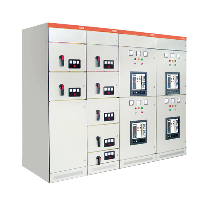
The GCK low-voltage switchgear consists of two parts: the Power Distribution Center (PC) cabinet and the Motor Control Center (MCC). It is suitable for power users such as power plants, substations, and industrial and mining enterprises. In power distribution systems with an AC frequency of 50Hz, a maximum operating voltage of up to 660V, and a maximum operating current of up to 3150A, it can be used for power conversion, distribution, and control of power distribution equipment such as power distribution, motor control, and lighting systems.
Model and Its Meaning

Main Features
1、The framework is made of section steel, positioned using 3D angle plates, and connected by bolts (weld-free structure). This avoids welding deformation and stress, improving installation accuracy.
2、The mounting holes of the framework and components vary according to the modulus E = 20mm.
3、Internal structural parts undergo galvanization treatment. The external surface is treated with pickling and phosphating, followed by electrostatic epoxy powder coating.
4、The functional unit of the drawer and the cabinet door are mechanically interlocked via the operating mechanism of the main switch. The door cannot be opened when the main switch is in the closed position; additionally, the operating mechanism can be locked in the closed or open position using an external padlock.
5、Functional unit compartments are separated by metal plates. Drawers feature excellent interchangeability and have three positions: operating position, test position, and disconnected position. When a drawer is pushed to a certain position, it automatically locks in place. At this point, the pull plate on the left side of the drawer can be pulled to release the lock, allowing the drawer to move to the next position. When the drawer is pulled out of the cabinet, it also has an anti-falling function.
5、Functional unit compartments are separated by metal plates. Drawers feature excellent interchangeability and have three positions: operating position, test position, and disconnected position. When a drawer is pushed to a certain position, it automatically locks in place. At this point, the pull plate on the left side of the drawer can be pulled to release the lock, allowing the drawer to move to the next position. When the drawer is pulled out of the cabinet, it also has an anti-falling function.
6、Fixed-scheme cabinets (for capacitor compensation, metering, etc.) share the same external design and horizontal busbar position as drawer-type cabinets. This ensures that drawer-type and fixed-type cabinets can be used side by side.
7、Busbar system: The cabinet adopts a three-phase five-wire system. For horizontal busbars with a rated current of 1250A or below, a single busbar is used; for those with a rated current above 1250A, a double busbar is adopted. Horizontal busbars between cabinets are connected via connecting blocks. Vertical busbars are enclosed in a polycarbonate engineering plastic shell, with internal partitions to restrict arc diffusion. The neutral busbar is installed at the front of the cabinet top, and the protective earth (PE) busbar is installed at the bottom of the cabinet, connected to the cabinet’s partitions and door—ensuring grounding continuity.
7、Busbar system: The cabinet adopts a three-phase five-wire system. For horizontal busbars with a rated current of 1250A or below, a single busbar is used; for those with a rated current above 1250A, a double busbar is adopted. Horizontal busbars between cabinets are connected via connecting blocks. Vertical busbars are enclosed in a polycarbonate engineering plastic shell, with internal partitions to restrict arc diffusion. The neutral busbar is installed at the front of the cabinet top, and the protective earth (PE) busbar is installed at the bottom of the cabinet, connected to the cabinet’s partitions and door—ensuring grounding continuity.
Technical Parameters of GCK Switchgear
Main Features
| Item | Parameter |
| Rated Operating Voltage (V) | 380、660 |
| Rated Insulation Voltage (V) | 660 |
| Rated Frequency (Hz) | 50 |
| Rated Operating Current (A) | Horizontal Busbar: 630~5000 Vertical Busbar: 600 |
| Rated Short-Time Withstand Current | Horizontal Busbar: 80kA (RMS) / 1s Vertical Busbar: 50kA (RMS) / 1s |
| Rated Peak Withstand Current | Horizontal Busbar: 176kA / 0.1s Vertical Busbar: 110kA / 0.1s |
| Power Frequency Test Voltage (V/1min) | Main Circuit: 2500 Auxiliary Circuit: 1760 |
| Main Circuit Connector (A) | 200、400、600 |
| Auxiliary Circuit Connector (A) | 10 |
1、Ambient air temperature: Not higher than +40℃ and not lower than -5℃; the average temperature within 24 hours shall not exceed +35℃. If this temperature is exceeded, the device shall be operated at a derated capacity based on actual conditions.
2、Indoor use: The altitude of the installation site shall not exceed 2000 meters.
3、Relative humidity of ambient air: Not more than 50% at +40℃; higher relative humidity is allowed at lower temperatures (e.g., 90% at +20℃). The impact of occasional condensation that may occur due to temperature changes shall be taken into account.
4、When installing the device, the inclination angle relative to the vertical plane shall not exceed 5 degrees, and the entire row of cabinets shall be relatively level (in compliance with the GBJ232-82 standard).
5、The device shall be installed in a location free from severe vibration, impact, and substances that could cause undue corrosion to electrical components.
6、Special requirements from users can be resolved through negotiation with the manufacturer.