
Product Introduction
I. Overview
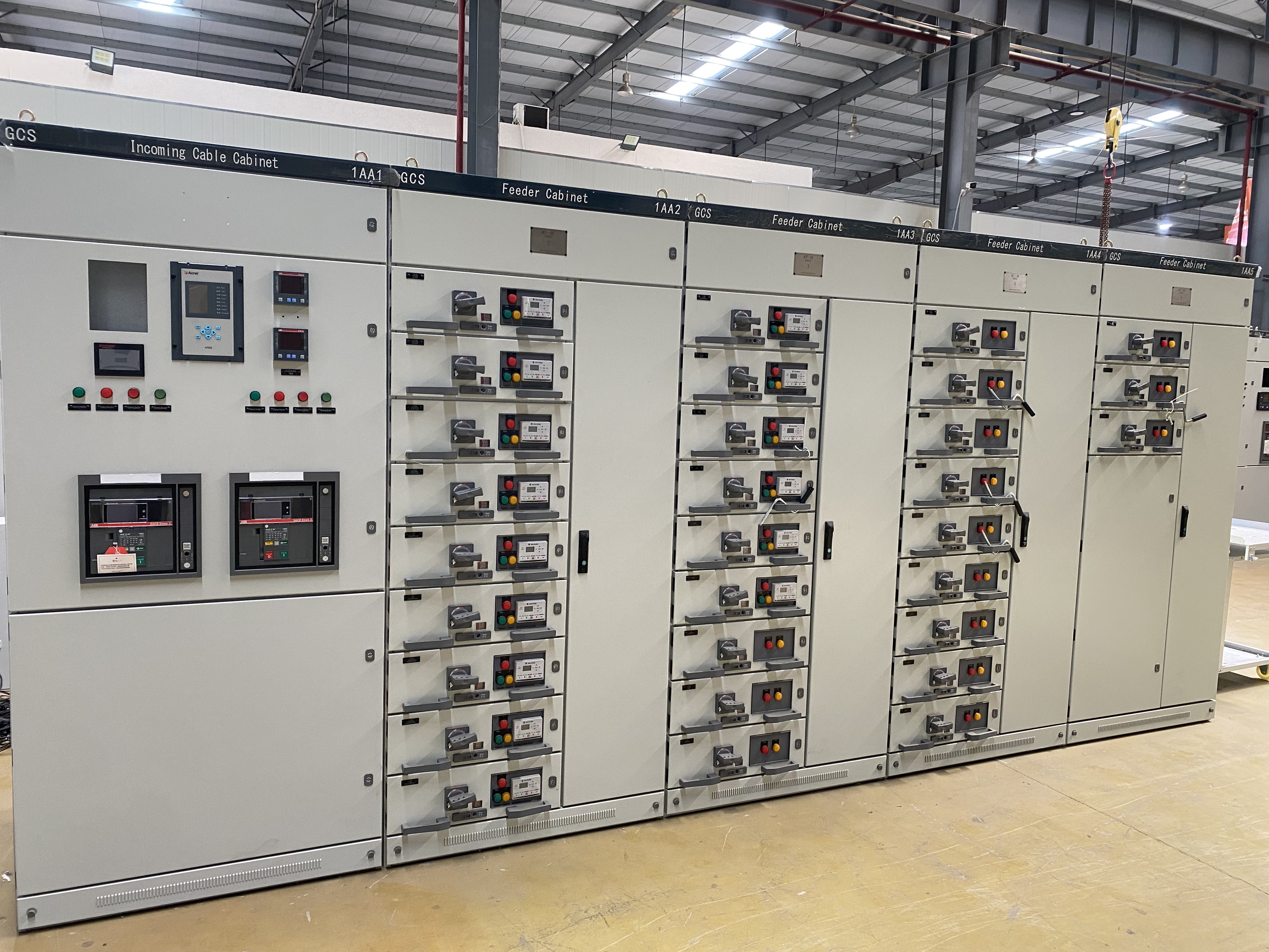
GCS is a type of power distribution equipment. The GCS-type low-voltage withdrawable switchgear (hereinafter referred to as "the equipment") is a low-voltage withdrawable switchgear developed by the Joint Design Team in response to the requirements of industry authorities, a large number of power users, and design institutions. It is in line with national conditions, features high technical performance indicators, can meet the development needs of the power market, and is competitive with existing imported products. This equipment has been widely selected and used by power users.
II. Model and Its Meaning

III. Operating Conditions
1. The ambient air temperature shall not exceed +40°C or be lower than -5°C. The average temperature within 24 hours shall not exceed +35°C. If the temperature exceeds this range, the equipment shall be operated at a derated capacity based on actual conditions.
2. For indoor use, the altitude of the installation site shall not exceed 2000m.
3. The relative humidity of the ambient air shall not exceed 50% when the maximum temperature is +40°C; higher relative humidity is allowed at lower temperatures (e.g., 90% at +20°C). The impact of occasional condensation caused by temperature changes shall be taken into account.
4. When installing the equipment, the inclination angle relative to the vertical plane shall not exceed 5°, and the entire row of cabinets shall be relatively flat (complying with GBJ 232-82 standard).
5. The equipment shall be installed in a location free from severe vibration, shock, and conditions that could cause undue corrosion to electrical components.
IV. Applicable Environments
It is suitable for power distribution systems in industries such as power plants, petroleum, chemical engineering, metallurgy, textiles, and high-rise buildings. In scenarios with high automation requirements that need interface with computers (e.g., large power plants, petrochemical systems), it serves as a low-voltage complete power distribution device for power distribution, centralized motor control, and reactive power compensation in power generation and supply systems with three-phase AC frequency of 50 (60) Hz, rated working voltage of 380V (400V), (600V), and rated current of 4000A or below.
It is suitable for power distribution systems in industries such as power plants, petroleum, chemical engineering, metallurgy, textiles, and high-rise buildings. In scenarios with high automation requirements that need interface with computers (e.g., large power plants, petrochemical systems), it serves as a low-voltage complete power distribution device for power distribution, centralized motor control, and reactive power compensation in power generation and supply systems with three-phase AC frequency of 50 (60) Hz, rated working voltage of 380V (400V), (600V), and rated current of 4000A or below.
V. Standard Requirements
- IEC 439-1 *Low-Voltage Switchgear and Controlgear Assemblies*
- GB 7251 *Low-Voltage Switchgear and Controlgear Assemblies*
- ZBK 36001 *Low-Voltage Withdrawable Switchgear Assemblies*
- IEC 439-1 *Low-Voltage Switchgear and Controlgear Assemblies*
- GB 7251 *Low-Voltage Switchgear and Controlgear Assemblies*
- ZBK 36001 *Low-Voltage Withdrawable Switchgear Assemblies*
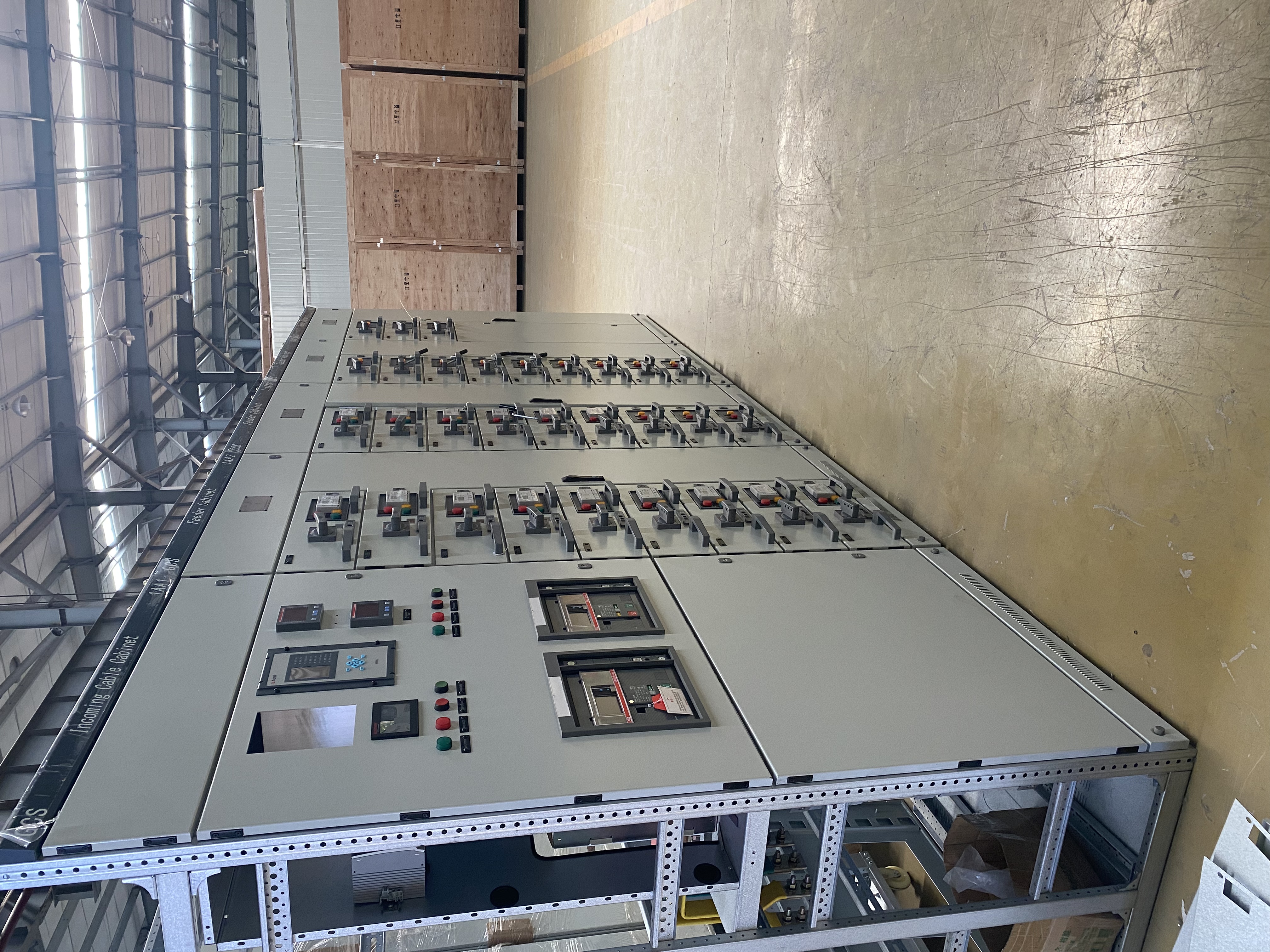
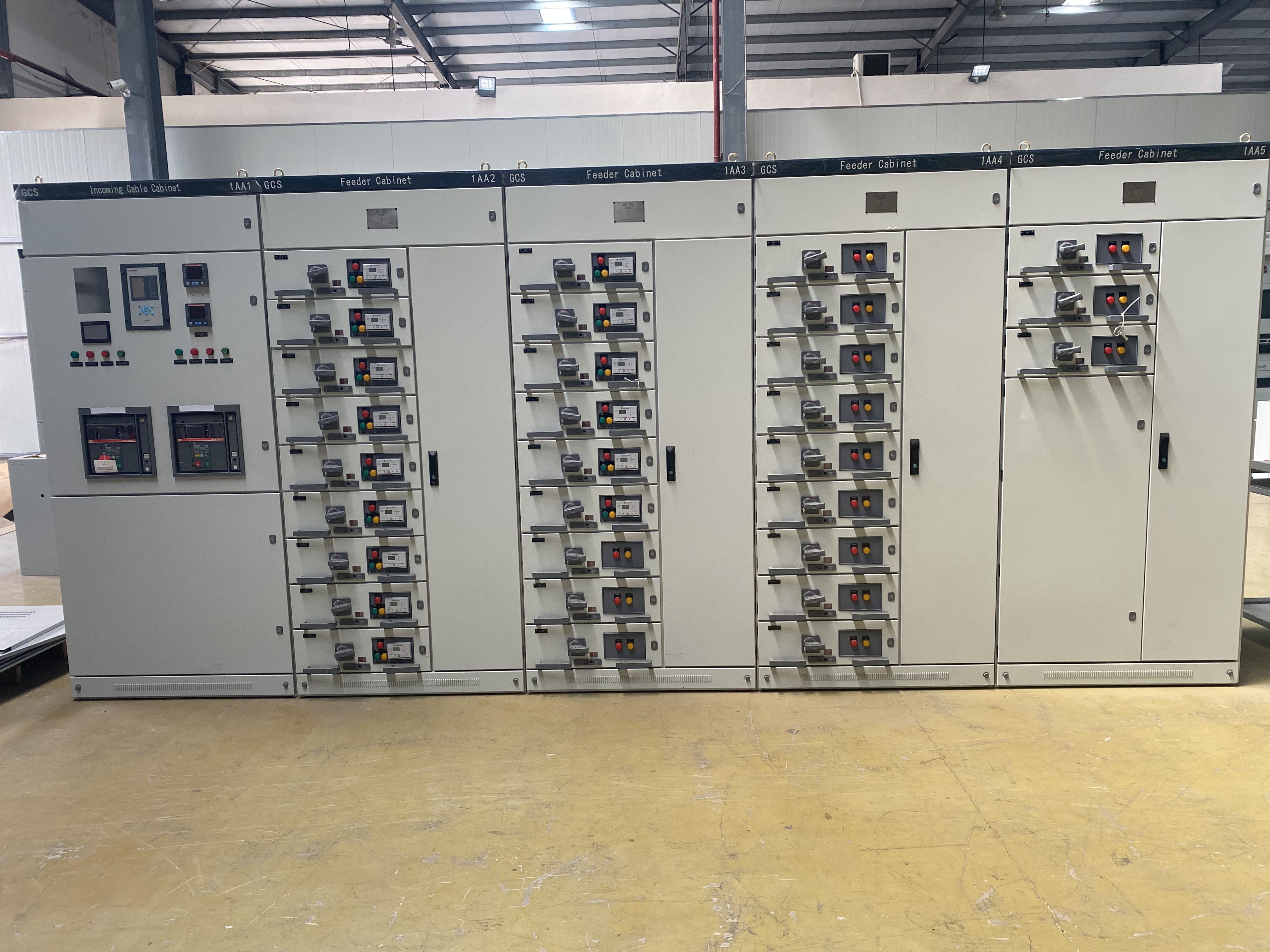
VI. Structural Features
1. The main frame of the equipment adopts 8MF section steel, with two structural forms: assembled and partially welded. All main frames are provided with mounting modular holes (E = 20mm).
2. The functional compartments of the equipment are strictly separated, mainly including the functional unit compartment, busbar compartment, and cable compartment. The functions of each unit are relatively independent.
3. Functional Units
a. The module of the drawer height is 160mm, divided into five size series: 1/2 unit, 1 unit, 1.5 units, 2 units, and 3 units. The rated current of the unit circuit is 400A or below.
b. Drawers only vary in height dimension, while their width and depth dimensions remain unchanged. Drawers of the same functional unit have good interchangeability.
c. Each GCS cabinet can accommodate a maximum of 11 single-unit drawers or 22 half-unit (1/2 unit) drawers. Drawers of 1 unit or larger adopt multi-functional back panels.
d. For the incoming and outgoing lines of drawers, connectors of the same specification with different numbers of plates are used according to the current magnitude.
e. The transfer between 1/2 unit drawers and the cable compartment adopts a backplane structure (ZJ-2 type transfer part).
f. The transfer between unit drawers and the cable compartment adopts rod-type or tube-type transfer parts of the same size (ZJ-1 type) classified by current levels. See Figure 6 for the outline of the transfer parts.
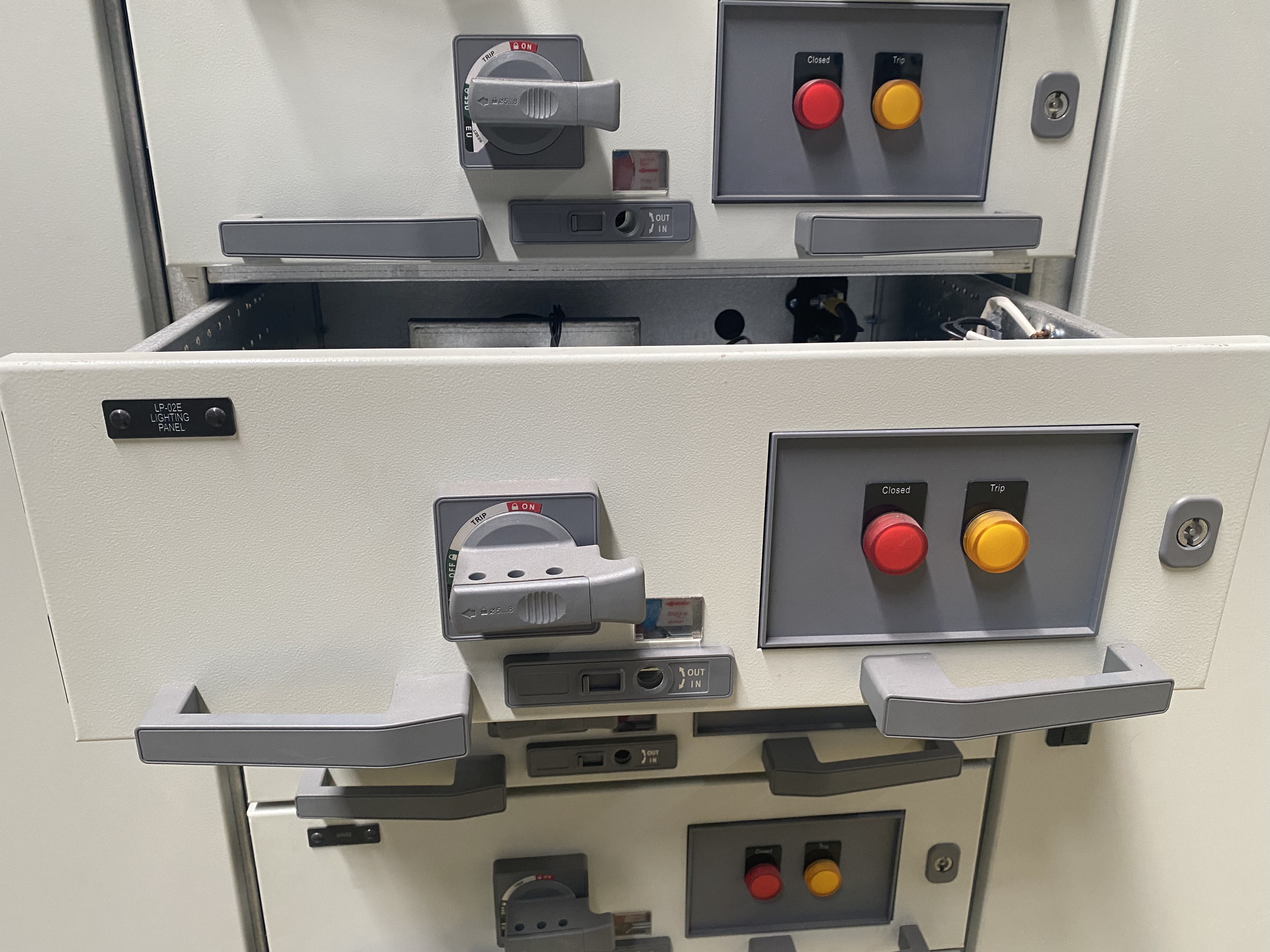
g. The drawer panel is provided with clear indicators for positions such as "Open", "Close", "Test", and "Withdrawn".
h. Drawer units are equipped with mechanical interlocking devices.
4. Feeder cabinets and motor control cabinets are provided with dedicated cable compartments. The connection between cables in the functional unit compartment and the cable compartment is realized through transfer parts or transfer copper bars, which not only improves the reliability of cable use but also greatly facilitates cable installation and maintenance for users. The cable compartment has two width dimensions (240mm and 440mm) for selection, depending on the number and cross-section of cables, as well as user requirements for installation and maintenance convenience.
5. The number of auxiliary contacts for the functional units of the equipment is 32 pairs for units of 1 unit or larger, and 20 pairs for 1/2 units, which can meet the interface needs of automated users with computers.
6. Considering the universality and safety of dry-type transformers and the economy of oil-immersed transformers, the equipment can be easily combined with dry-type transformers into a cabinet row, and can also be conveniently connected to the low-voltage busbar of oil-immersed transformers.
7. With drawers as the main component, the equipment features both withdrawable and fixed types, which can be mixed and combined for arbitrary selection.
8. The equipment is designed for three-phase five-wire system and three-phase four-wire system, allowing design institutions and users to easily select the PE+N or PEN mode.
9. The cabinet protection class is IP30 or IP40, which can be selected according to user needs.
1. The main frame of the equipment adopts 8MF section steel, with two structural forms: assembled and partially welded. All main frames are provided with mounting modular holes (E = 20mm).
2. The functional compartments of the equipment are strictly separated, mainly including the functional unit compartment, busbar compartment, and cable compartment. The functions of each unit are relatively independent.
3. Functional Units
a. The module of the drawer height is 160mm, divided into five size series: 1/2 unit, 1 unit, 1.5 units, 2 units, and 3 units. The rated current of the unit circuit is 400A or below.
b. Drawers only vary in height dimension, while their width and depth dimensions remain unchanged. Drawers of the same functional unit have good interchangeability.
c. Each GCS cabinet can accommodate a maximum of 11 single-unit drawers or 22 half-unit (1/2 unit) drawers. Drawers of 1 unit or larger adopt multi-functional back panels.
d. For the incoming and outgoing lines of drawers, connectors of the same specification with different numbers of plates are used according to the current magnitude.
e. The transfer between 1/2 unit drawers and the cable compartment adopts a backplane structure (ZJ-2 type transfer part).
f. The transfer between unit drawers and the cable compartment adopts rod-type or tube-type transfer parts of the same size (ZJ-1 type) classified by current levels. See Figure 6 for the outline of the transfer parts.
g. The drawer panel is provided with clear indicators for positions such as "Open", "Close", "Test", and "Withdrawn".
h. Drawer units are equipped with mechanical interlocking devices.
4. Feeder cabinets and motor control cabinets are provided with dedicated cable compartments. The connection between cables in the functional unit compartment and the cable compartment is realized through transfer parts or transfer copper bars, which not only improves the reliability of cable use but also greatly facilitates cable installation and maintenance for users. The cable compartment has two width dimensions (240mm and 440mm) for selection, depending on the number and cross-section of cables, as well as user requirements for installation and maintenance convenience.
5. The number of auxiliary contacts for the functional units of the equipment is 32 pairs for units of 1 unit or larger, and 20 pairs for 1/2 units, which can meet the interface needs of automated users with computers.
6. Considering the universality and safety of dry-type transformers and the economy of oil-immersed transformers, the equipment can be easily combined with dry-type transformers into a cabinet row, and can also be conveniently connected to the low-voltage busbar of oil-immersed transformers.
7. With drawers as the main component, the equipment features both withdrawable and fixed types, which can be mixed and combined for arbitrary selection.
8. The equipment is designed for three-phase five-wire system and three-phase four-wire system, allowing design institutions and users to easily select the PE+N or PEN mode.
9. The cabinet protection class is IP30 or IP40, which can be selected according to user needs.
VII. Product Features
1. It increases the thermal capacity of transfer parts, significantly reducing the additional temperature rise of connectors, cable terminals, and partition plates caused by the temperature rise of transfer parts.
2. The separation between functional units and between compartments is clear and reliable; the failure of one unit will not affect the operation of other units, confining faults to the minimum scope.
3. The horizontal arrangement of busbars ensures good dynamic and thermal stability of the equipment, enabling it to withstand the impact of short-circuit current of 80/176kA.
4. The number of circuits in a single MCC (Motor Control Center) cabinet can be as many as 22, fully meeting the needs of automated motor groups in industries such as large single-unit capacity power generation and petrochemical systems.
5. The connection between the equipment and external cables is completed in the cable compartment; cables can enter and exit from the top or bottom. The zero-sequence current transformer is placed in the cable compartment, facilitating installation and maintenance.
6. For the same power supply and distribution system, short-circuit current can be limited through matching with current-limiting reactors, stabilizing the busbar voltage within a certain range, and partially reducing the short-circuit strength requirements for components.
7. Drawer units are equipped with a sufficient number of secondary connectors (32 pairs for units of 1 unit or larger, 20 pairs for 1/2 units), which can meet the requirements for the number of contacts in computer interfaces and automatic control circuits.